Table of Contents
Optimization of EMC Protection Design for PLC Panel
- Betty
Introduction
Why is EMC Protection Crucial for PLC Panels?
In today’s complex industrial environment filled with electrical interferences, the Programmable Logic Controller panel (PLC panel), serving as the core hub of the automation control system, shoulders the heavy responsibility of precise control and reliable operation.
However, electromagnetic compatibility (EMC) issues such as electromagnetic interference (EMI) from surrounding electrical devices and communication systems, as well as electrostatic discharge (ESD), are like hidden hazards that constantly threaten the normal operation of the PLC panel. Once the PLC panel is affected by electromagnetic interference, it may not only lead to a decrease in control accuracy and errors in data transmission, but also trigger equipment shutdown, causing production interruptions and huge economic losses.
Therefore, effective EMC protection is crucial for ensuring the stable and reliable operation of the PLC panel in a harsh electromagnetic environment. It is a key link in ensuring the efficient and safe operation of the industrial automation system.
Three Major Electromagnetic Interference Propagation Paths and Countermeasures
Conductive Interference
Noise introduced through power lines and signal lines (filtering and isolation are required)
Filtering
- Power Supply Filtering:
Install a power supply filter at the power input terminal of the PLC control cabinet to filter out high-frequency interference signals in the power supply. This power supply filter should have excellent common-mode and differential-mode suppression capabilities, and be able to effectively suppress the noise and surges in the power grid.
- Signal Filtering
For analog signals and digital signals that are vulnerable to interference, install signal filters at the signal input or output terminals. Signal filters can be selected according to the frequency characteristics of the signals, such as low-pass filters, high-pass filters, or band-pass filters, to filter out interference signals within a specific frequency range.
Isolation
- Electrical Isolation:
Use isolation transformers, optocouplers, etc. to perform electrical isolation between the PLC panel and external devices, cutting off the propagation path of interference signals. The isolation transformer can isolate the common-mode interference in the power supply, and the optocoupler can isolate the electrical connections in the input and output signals, preventing the transmission of interference signals.
- Regional Isolation:
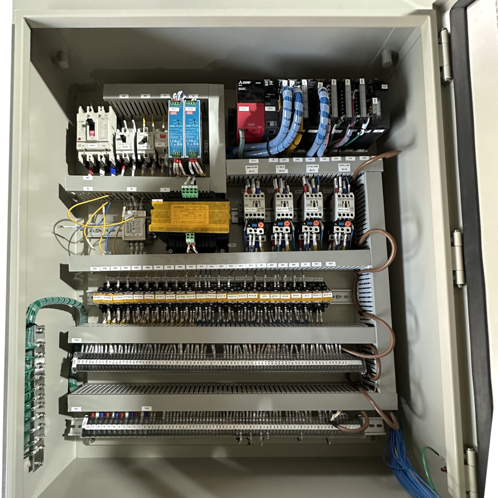
Physically isolate different functional areas inside the PLC cabinet. For example, arrange the strong current part and the weak current part separately to reduce the electromagnetic coupling interference between them.
Radiation Interference
Interference to the PLC from spatial electromagnetic waves (shielding and grounding are required)
Shielding
- Enclosure Shielding:
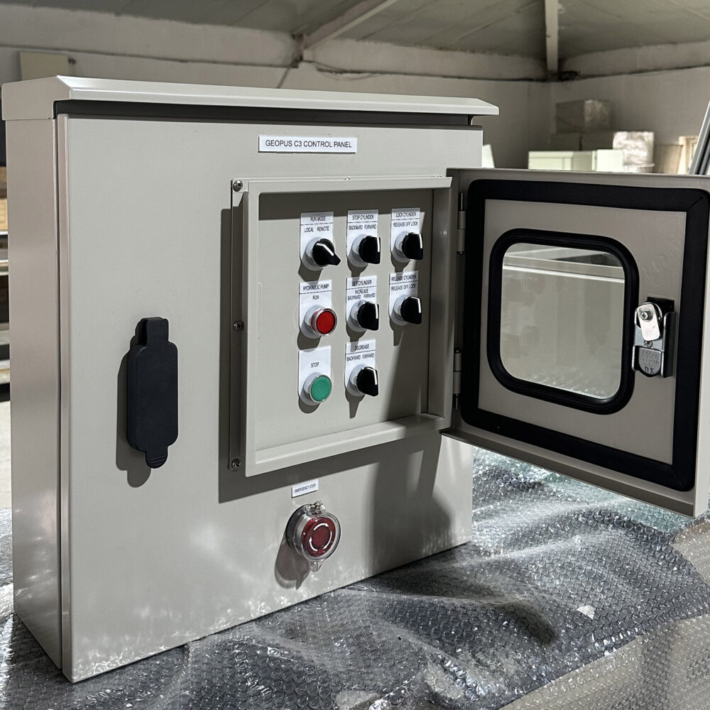
Use metal materials with good conductivity (such as steel plates or aluminum plates) to make the control cabinet enclosure, forming a complete shielding body. The joints of the enclosure should be tightly connected, using conductive gaskets or bolts for fastening to reduce electromagnetic leakage. For cable entrances and exits, install shielded cable entry devices to ensure good connection between the cable shielding layer and the cabinet body.
- Treatment of Observation Windows and Ventilation Openings:
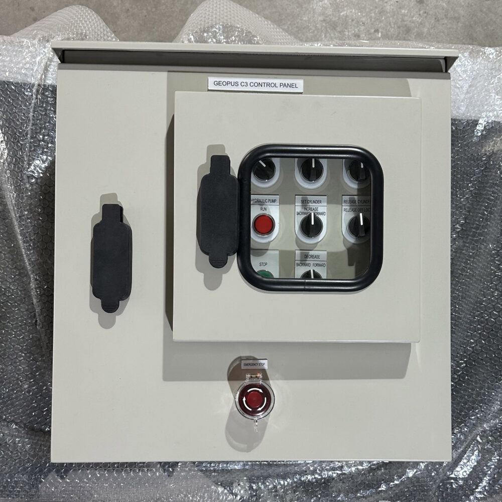
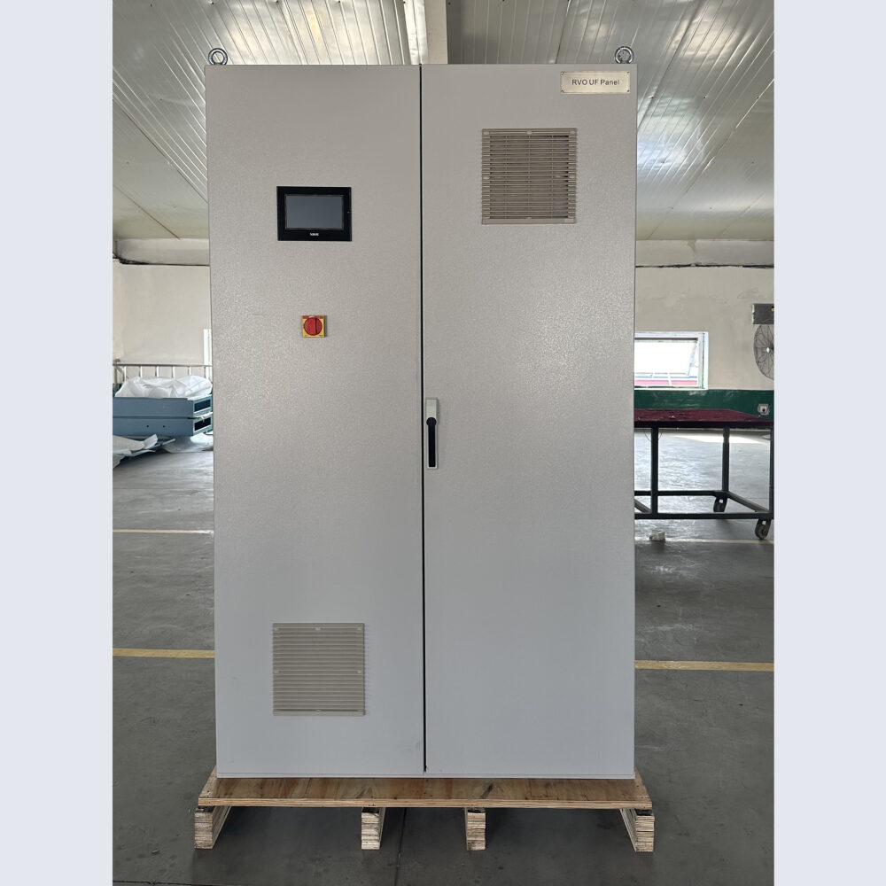
If the control cabinet has an observation window, use glass with a conductive coating or transparent conductive materials to maintain the shielding effect. For ventilation openings, install metal wire meshes or waveguide ventilation panels to prevent electromagnetic interference from entering or escaping through the ventilation openings.
Coupling Interference
Electromagnetic induction between cables or devices (optimize wiring)、Cable Selection and Wiring
Cable Selection and Wiring
- Cable Selection:
Select appropriate cables according to the signal type and transmission requirements. For sensitive analog signals and high – speed digital signals, use shielded cables; for power cables, choose cables with good insulation performance and anti – interference ability.
- Cable Wiring:
Route power cables, control cables, and signal cables separately to avoid mutual interference. Power cables should be kept as far away from signal cables as possible, and the distance between them should meet relevant standard requirements. If crossing is unavoidable, use a vertical crossing method. At the same time, the cables should be neatly arranged and firmly fixed to reduce electromagnetic interference caused by cable shaking and friction.
Optimal Layout
- Equipment Layout:
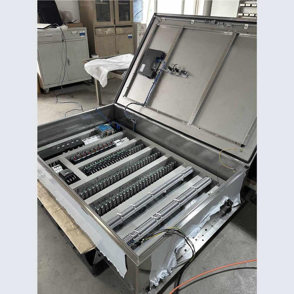
Reasonably arrange equipment such as PLCs, various modules, relays, and contactors inside the PLC panels. Install high – heat – generating equipment separately from temperature – sensitive equipment to prevent high temperatures from affecting the performance of the equipment. At the same time, consider the electromagnetic compatibility between equipment to avoid interference from strong electromagnetic fields on sensitive equipment.
- Routing Layout:
The wiring inside the PLC panel should be neat and standardized, avoiding cable crossing and entanglement. Signal lines should be as short as possible to reduce signal transmission losses and interference. For high – frequency signal lines, use cables with matched characteristic impedance, and pay attention to the shielding and grounding of the signal lines.
Related article
