Table of Contents
How to Build a PLC Cabinet: A Step-by-Step Guide
- Betty
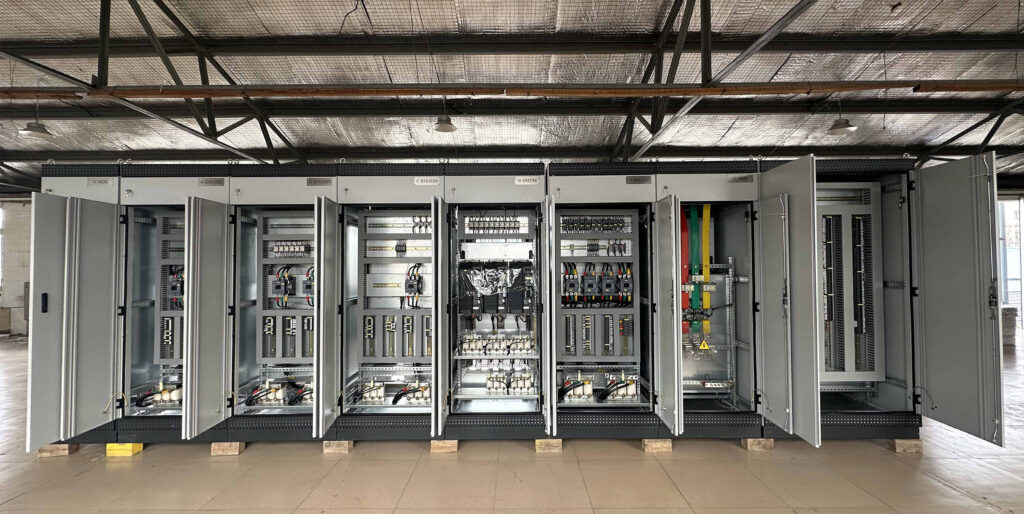
Figure No.1 PLC Cabinet Customer Case
The PLC cabinet serves as the “brain” of the industrial automation system, taking charge of controlling and managing the operation of production equipment. Whether it is a small production line or a complex industrial system, the PLC cabinet plays a vital role.
This article will guide you through the process of building an efficient and reliable PLC cabinet from scratch step by step, covering the entire process of planning, design, installation, debugging, and maintenance.
Step 1: Design the PLC cabinet Layout
Before designing the layout, you must have a comprehensive understanding of the specific requirements of the project and the electrical components that will be used in the control panel of the PLC cabinet. This step is the foundation of the design and determines all the subsequent work.
Clarify System Requirements
Determine the type and quantity of the PLC, and select suitable I/O modules, communication modules, and power supply devices.
Calculate the power requirements according to the equipment load to ensure that the power capacity is sufficient to support all components.
Determine the communication protocol (such as Modbus, Profibus, Ethernet, etc.) to enable seamless connection between the PLC and other devices.
List the Component Inventory
It includes the PLC, power supply modules, circuit breakers, relays, terminal blocks, HMI (Human-Machine Interface), etc.
Take into account the possible future expansion needs and reserve enough space and interfaces.
An optimized layout can not only improve the system performance but also significantly reduce the cost !!!
When designing the layout, we should always follow the following core principles to ensure the efficiency and reliability of the PLC cabinet:
- Group the components according to their functions and the relationships among them. For example, place the power supply devices centrally and install the I/O modules close to the PLC.
- Make the most of the space inside the cabinet, and reserve 20%-30% of the space for future expansion at the same time.
- Ensure that the heat-generating components have sufficient heat dissipation space, and arrange the ventilation equipment reasonably.
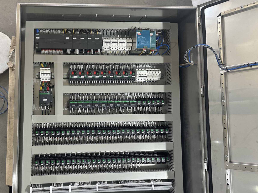
Figure No.2 PLC Cabinet Internal Wiring
Step 2: Select Electrical Components
When selecting electrical components, you should consider not only their performance but also their economy and maintainability.
On the premise of meeting the performance requirements, choose components with high cost-effectiveness to reduce the project cost.
Select standardized and modular components to facilitate replacement and maintenance.
PLC and I/O modules:
The PLC is the core of the control cabinet, and the choice of the PLC directly affects the performance and expansion capability of the system.
We should select the appropriate PLC model according to the complexity of the control task.
Select the appropriate I/O modules according to the types (such as digital quantity and analog quantity) and the quantity of the input and output signals.
Power Supply Equipment:
To provide stable power for the plc cabinet, we need to select a suitable power module according to the total power requirement of the system to ensure sufficient power supply. At the same time, consider the efficiency, heat dissipation and protection level of the module to ensure its stable operation in various environments.
In critical applications, we can also use an Uninterruptible Power Supply (UPS) or backup batteries to prevent the system from stopping operation during a power outage.
Protection Equipment:
It can prevent electrical failures from damaging the system and is crucial to the safety of the system. We must select appropriate circuit breakers and fuses according to the circuit current to ensure that the power can be cut off in a timely manner in case of overload or short circuit.
Communicaion Equipment:
It is used to achieve data exchange between the PLC and other devices. We need to select appropriate communication protocols (such as Modbus, Profibus, Ethernet, etc.) and communication modules according to the system requirements.
In large-scale systems, we will use network devices such as switches and routers to build a reliable communication network.
Human-Machine Interface:
It is used to operate and monitor the system and affects the user experience and operation efficiency. Select an appropriate model according to the complexity of the operation, such as a touch screen, button panel, etc.
At the same time, we also need to ensure that the HMI is compatible with the software of the PLC and other devices to facilitate system integration and data exchange.
In addition to the core devices, some auxiliary devices are also needed in the PLC cabinet to improve the performance and reliability of the system.
For example, select appropriate heat dissipation devices according to the heat generation inside the cabinet, such as fans, heat sinks, or air conditioners.
Ensure that the heat dissipation devices can effectively reduce the temperature inside the cabinet and prevent the components from overheating.
Install lighting devices inside the control cabinet to facilitate operation and maintenance when the light is insufficient.
Step 3: Create Electrical Schematics
After communicating with the users, we will clarify the control objectives and determine the logical functions that the PLC cabinet needs to achieve. Then we will list the required component inventory and start to draw the framework structure.
Drawing the framework structure includes:
Main Circuit: Draw the power supply path of the power equipment (motors, drivers), and mark the protective components such as circuit breakers and contactors.
Control Circuit: Include the logical control parts such as PLC, relays, and HMI, and clarify the signal flow direction.
Divide Functional Modules: Divide the system into power modules, PLC modules, I/O modules, communication modules, etc., draw them on separate pages and establish cross-references.
During the drawing process, we will use some symbols for marking.
We always follow the IEC/GB electrical symbol standards (such as coil, contact, and PLC terminal symbols).
At the same time, don’t forget to mark the key parameters, such as the voltage level, wire diameter specification, PLC terminal address, etc.
After the detailed electrical schematic diagram design is completed, we will use the PLC programming software to simulate the signal input and output to verify whether the logic of the schematic diagram is correct.
Through the above process, the electrical schematic diagram will become the core basis for the design, installation, and debugging of the PLC control cabinet, ensuring that the system is safe, reliable, and easy to maintain.
Step 4: Fabricate the Control Panel Enclosure
The manufacturing of the PLC Cabinet enclosure is a crucial step from protective design to process implementation.
A sturdy enclosure can provide a sealed environment for the internal PLC control panel, which is dustproof, waterproof, shock – resistant, corrosion – resistant, offers electromagnetic shielding and electrical isolation, and enables temperature and humidity management.

Figure No.3 Metal PLC Control Panel Enclosure
In the manufacturing of PLC cabinet enclosures, there are a wide variety of material options. At Yinlu, we often use metal materials, such as stainless steel and cold-rolled steel. However, the materials for PLC cabinet enclosures are not limited to these two.
Yinlu is a manufacturer that has been specializing in the custom sheet metal fabrication industry for 30 years. So, at this stage of PLC cabinet enclosure manufacturing, you can completely trust us with the task.
We have the capabilities of laser cutting, CNC bending, welding, and surface treatment. Yinlu ensures that the enclosures we produce meet all relevant industry standards and certifications.
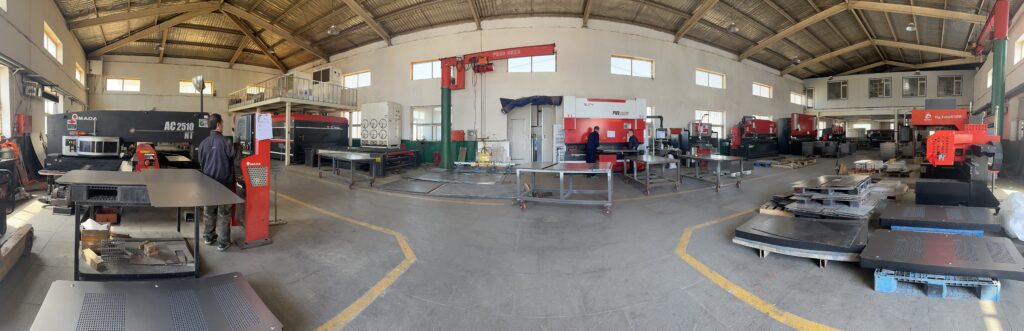
Figure No.4 Sheet Metal Fabrication Workshop
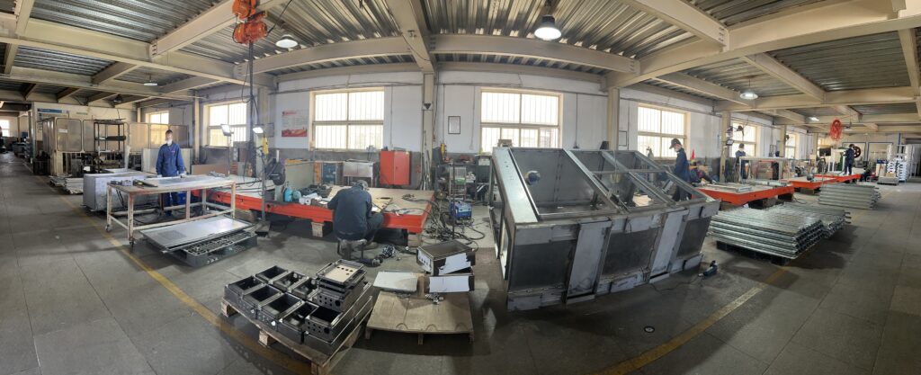
Figure No.5 Welding Workshop
Tips
In addition, pay attention to the structural design of the PLC cabinet enclosure:
Internal space:
Reserve more than 20% of expansion space and ensure that the opening angle of the maintenance door is ≥ 90°.
Installation compatibility:
Follow the standard DIN rail mounting slots and adjustable brackets to adapt to PLC modules of different brands.
Modular design:
Adopt a split – type structure as much as possible (such as removable top covers and side panels) to facilitate later upgrades or maintenance.
Step 5: Install the Components
During the process of installing components, you must be very careful.
Use appropriate screws, nuts, and washers to fix the components onto the DIN rail or brackets.
After that, connect the power supply to the PLC cabinet and make sure it is properly grounded.
When installing the I/O modules, use suitable wires and connectors to connect the I/O modules to the PLC and field devices. During installation, clearly mark the I/O points to facilitate troubleshooting and maintenance.
If the PLC needs to communicate with other devices, use appropriate wires and protocols for connection.
When fixing the internal components, be sure to follow the following principles:
- Place the power module that generates the most heat in the heat dissipation area at the top of the cabinet. Install the PLC processor in the middle for easy signal transmission, and leave the bottom for cable routing.
- Reserve at least two units of width as an isolation zone between the PLC and the frequency converter. This approach can resist electromagnetic interference.
Step 6: Wire the PLC Cabinet
Plan the wiring:
Before starting the wiring, plan in advance the routes of the wires and cables inside the PLC cabinet. Use wire ducts or cable ties reasonably to organize the wires and prevent mutual interference.
Strip and connect the wires:
Strip the insulation layer at the ends of the wires and use appropriate connectors to make the connections.
Mark the wires:
Mark the wires clearly to identify their functions and connection points. Use wire identification plates or labels to mark both ends of the wires.
Arrange the wires:
According to the planned wiring routes, thread the wires through the wire ducts, ensuring that the wires will not be damaged or squeezed during the wiring process. Use cable gland connectors or connectors to seal the openings on the control cabinet to prevent dust and moisture from entering.
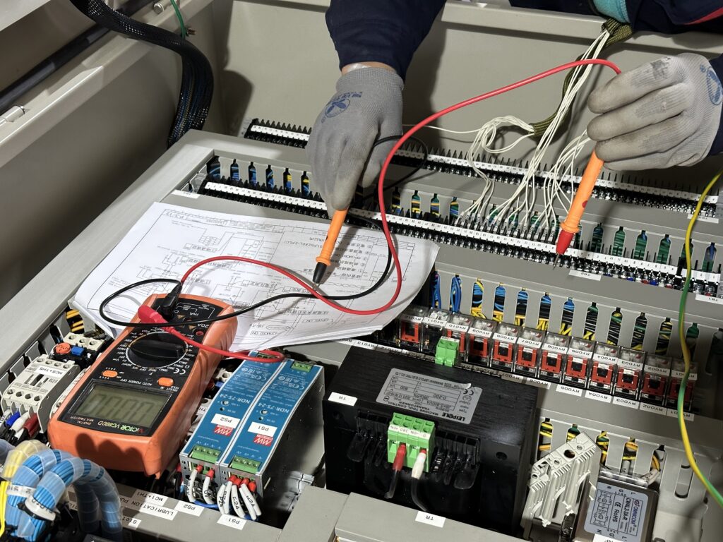
Figure No.7 Mount Components and Wiring
Step 7: Test and commissioning of PLC cabinets
- Check the wiring
Before powering on the PLC cabinet, we must carefully check the wiring to ensure that all connections are correct and secure. We can use a tester such as a multimeter to check for open circuits or short circuits.
- Power on the PLC cabinet
If there are no problems with the wiring after the check, we can start to power on the PLC cabinet. At this time, we can verify whether the internal components are operating normally. We need to check the status indicators on the PLC and other components to ensure that they are all in the normal operating state.
- Test the I/O points
Use test equipment or simulators to test the input and output points of the PLC. Verify whether the PLC receives the correct input signals and sends out corresponding output signals.
- Configure the PLC
Use the programming software provided by the PLC manufacturer to download the program to the PLC and set the parameters.
Conclusion
A meticulously crafted PLC cabinet can not only ensure the stable and efficient operation of the industrial automation system, but also enhance safety and simplify maintenance work.
If you are planning to build a PLC cabinet for your own automation needs, or you want to upgrade the existing one, you can contact us immediately to obtain comprehensive guidance and customized solutions that meet your specific requirements for the PLC cabinet.
